Monitoring my garden's limited sunlight time period with an Arduino (and some tupperware)
My house has a lovely little garden out front. The house and garden itself are elevated one storey above the street (and so my basement is really more of a bizarre ground floor because it has natural light windows but is full of dust and my life-accumulated rubbish is in one room of it while my covid-times "trying to stay fit, not fat" home gym is in the other) and there was no fence around it when I moved in. Meaning that that the interesting characters that amble past (suffice to say that I went for a nicer house in a slightly on-the-cusp between classy and rougher neighbourhoods as opposed to a less nice house in a posh place) could see in and converse between sips on their 9am double-strength lager. Once fenced off, kitted out with a cute little table and chairs that my friendly neighbours found at a tip and with some lovely raised flower beds installed, it is a delight in Summer.. only problem is that my house faces the wrong way and so only gets direct sunlight at certain hours of the day. And this time period varies greatly depending upon the time of year - in March, it might not get the light until almost 5pm whilst in July and August it's getting warm and light and beautiful (well, on the days that English weather allows) more in time for a late lunch.
The problem is that, even after four years here, I still don't really have any idea when it's going to be sunny there for a given time of year and I want to be able to plan opportunities around it - late evening drinks outside with friends, lunch time warm weather meals for myself, just any general chance top up my vitamin D!
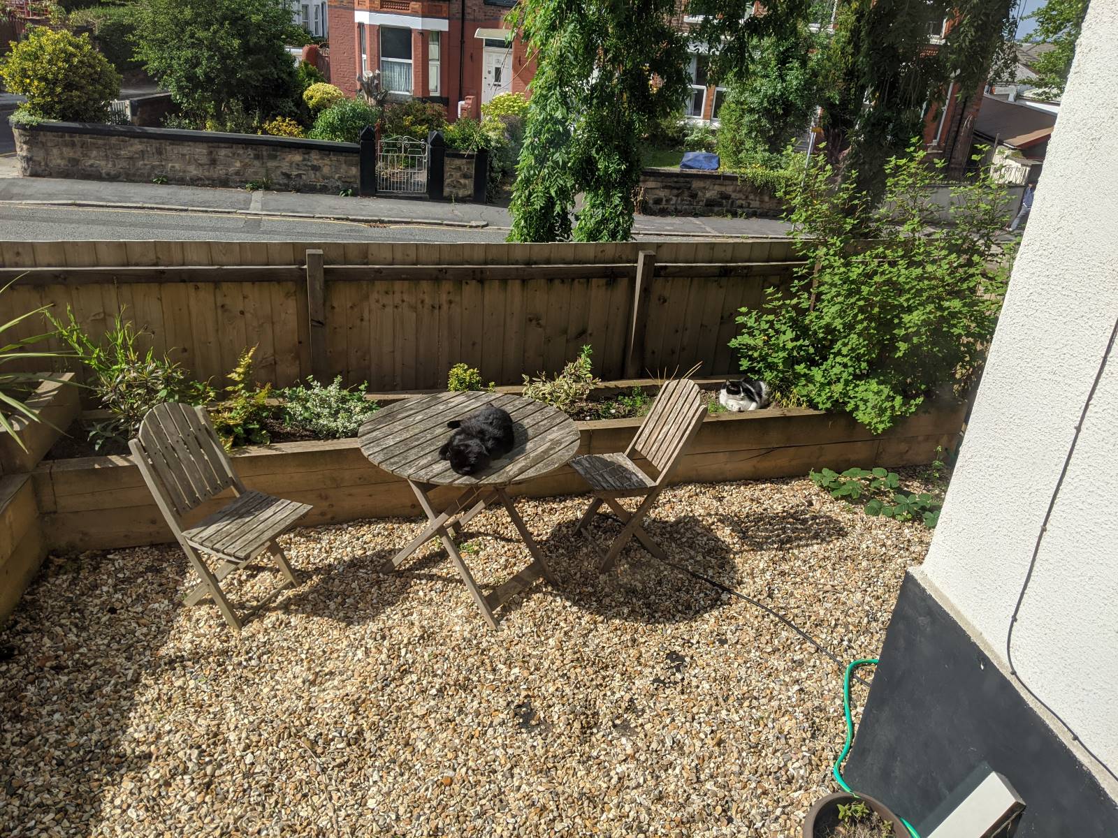
I guess that one way to sort this out would be to just keep an eye out on sunny days and take the opportunity whenever it strikes. A more organised plan would be to start a little diary and mark down every fortnight or so through the year when the sun hits the garden and when it leaves.
But I work in technology, damnnit, and so I expect to be able to solve this using that electronics and magic! (Cue comments about everything looking like a nail when you're holding a hammer).
To be really honest, maybe I'm describing this situation back to front. My friend gave me an Arduino UNO r3 because he had a kit spare from the coding club that he runs for kids locally and I'd been looking for a use for it.. and this seemed like it!
What I needed
Being a total Arduino noob (and, since my Electronics GCSE was over 20 years ago now, I'm basically a total hardware noob.. you should have seen the trouble that I had trying to build a custom PC a few years ago; I swear it was easier when I was 14!) I wanted something nice and simple to begin with.
So I had the starter kit, which included the Arduino board and some jumper cables, a prototyping breadboard and some common components (including, essentially, a photoresistor) and so I figured that all I'd then need is a way to record the light levels periodically, a power source and some sort of container for when it rains (again; England).
I considered having some sort of fancy wifi server in it that would record the values somehow and let me either poll it from somewhere else or have it push those results to the cloud somewhere but eventually decided to go for what seemed like a simpler, more robust and (presumably) more power efficient mechanism of storing the light values throughout the day - using an SD card. Because I'd got the kit for free (on the agreement that I would try to do something useful with it), I was looking for something cheap to write to an SD card that I'd had lying around since.. well, I guess since whenever SD cards were useful. Could it have been a digital camera? The very concept seems absurd these days, with the quality of camera that even phones from three or four generations ago have.
I came across something called a "Deek Robot SD/RTC datalogging shield" that would not only write to an SD card but would also keep time due to a small battery mounted on it.
These are cheap (mine was less than £5 delivered, new from eBay) but documentation is somewhat.. spotty. There is a lot of documentation for the "Adafruit Assembled Data Logging shield" but they cost more like £13+ and I was looking for the cheap option. Considering how much time I spent trying to make it work and find good information, it probably would have made more sense to buy a better supported shield than a knock-off from somewhere.. but I did get it working eventually, so I'll share all the code throughout this post!
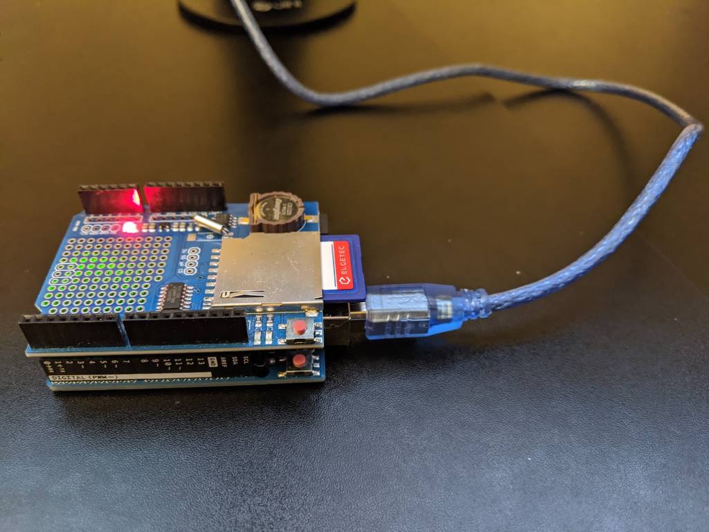
Note: I found a warning that when using this particular shield, "If you have a UNO with a USB type B connector this shield may NOT WORK because the male pins are NOT LONG ENOUGH" on a forum page - my UNO r3 does have the USB B connector but I've not had this problem.. though if you do encounter this problem then maybe some sort of pin extenders or raisers would fix it.
Step 1: Writing to the SD card
After reading around, I settled on a library called SdFat that should handle the disk access for me. I downloaded it from the Github repo and followed the "Importing a .zip Library" instructions on the Installing Additional Arduino Libraries page.
This allowed me to stack the data logging shield on top of the UNO, put an SD card into the shield, connect the UNO to my PC via a USB lead and upload the following code -
#include <SdFat.h> // https://github.com/greiman/SdFat

// chipSelect = 10 according to "Item description" section of
// https://www.play-zone.ch/de/dk-data-logging-shield-v1-0.html
#define SD_CHIP_SELECT 10

void setup() {
  Serial.begin(9600);

  // See "Note 1" further down about SPI_HALF_SPEED
  SdFat sd;
  if (!sd.begin(SD_CHIP_SELECT, SPI_HALF_SPEED)) {
    Serial.println("ERROR: sd.begin() failed");
  }
  else {
    SdFile file;
    if (!file.open("TestData.txt", O_WRITE | O_APPEND | O_CREAT)) {
      Serial.println("ERROR: file.open() failed - unable to write");
    }
    else {
      file.println("Hi!");
      file.close();
      Serial.println("Successfully wrote to file!");
    }
  }
}

void loop() { }
The Arduino IDE has an option to view the serial output (the messages written to "Serial.println") by going to Tools / Serial Monitor. Ensure that the baud rate shown near the bottom right of the window is set to 9600 to match the setting in the code above.
This happily showed
Successfully wrote to file!
in the Serial Monitor's output and when I yanked the card out and put it into my laptop to see if it had worked, it did indeed have a file on it called "TestData.txt" with a single line saying "Hi!" - an excellent start!
Note 1: In the "sd.begin" call, I specify SPI_HALF_SPEED primarily because that's what most of the examples that I've found use - there is an option SPI_FULL_SPEED but I read in an Arduino forum thread that: "You should be able to use SPI_FULL_SPEED instead, but if that produces communication errors you can use SD_SCK_HZ(4 * MHZ) instead of SPI_HALF_SPEED" and I'm not sure what might be the limiting factor with said communication errors; whether it's the card or the shield or something else and I'm only going to be writing small amounts of data at relatively infrequent intervals and so I thought that I would err on the safe side and stick with SPI_HALF_SPEED.
Note 2: In a lot of code samples, in the "setup" method you will see code after the "Serial.begin(..)" call that looks like this:
while (!Serial) {
  // wait for serial port to connect - needed for native USB
}
^ This is only needed for particular variants of the Arduino - the "Leonardo", I believe - and is not required for the UNO and so I haven't included it in my code.
Gotcha One: Initially, I had formatted my SD card (branded as "Elgetec", who I can't remember ever hearing of other than on this card) on my Windows laptop - doing a full format, to make absolutely sure that it was as ready for action as possible. However, not only did that full format take a long time, I found that when I left my Arduino shield writing files over a period of a few hours then it would often get reported as being corrupted when I tried to read it. I've found that if the SdFormatter.ino (from the examples folder of the SdFat GitHub repo) is used then these corruption problems have stopped occurring (and the formatting is much faster!).
Gotcha Two: While I was fiddling around with writing to the SD card, particularly when connected to a battery instead of the USB port (where I could use the Serial Monitor to see what was happening), I tried setting the LED_BUILTIN to be on while writing and then go off again when the file was closed. This didn't work. And it can't work, though it took me a lot of reading to find out why. It turns out that the SPI (the Serial Peripheral Library) connection from the Arduino to the Deek Robot shield will use IO pins 10, 11, 12 and 13 for its own communications. 13 happens to be the output used to set the LED_BUILTIN state and so you lose access to setting that built-in LED while this shield is connected. Specifically, "pin 13 is the SPI clock. Pin 13 is also the built-in led and hence you have a conflict".
Step 2: Keeping time
Since I want to record light levels throughout the day, it's important to know at what time the recording is being made. The shield that I'm using also includes an "RTC" (a real-time clock) and so I needed to work out how to set that once and then read from it each time I took a light level reading.
The UNO board itself can do some basic form of time keeping, such as telling you how long it's been since the board started / was last reset (via the millis() function) but there are a few limitations with this. You can bake into the compiled code the time at which it was compiled and you could then use that, in combination with "millis()", to work out the current time but you will hit problems if power is temporarily lost or if the board is reset (because "millis()" will start from zero again and timing will start again from that baked-in "compiled at" time).
Gotcha Three: I didn't realise when I was first fiddling with this that any time you connected the USB lead, it would reset the board and the program (the "sketch", in Arduino-speak) would start all over again. (This will only make a difference if you're using an external power source because otherwise the program would stop whenever you disconnected the USB lead and there would be nothing running to reset when plugging the USB lead back in! I'll be talking about external power supplies further down).
So the next step was using the clock on the shield that I had bought, instead of relying on the clock on the Arduino board itself. To do this, I'd inserted a CR1220 battery and then tested with the following code:
#include <Wire.h>
#include <RTClib.h> // https://github.com/adafruit/RTClib

RTC_DS1307 rtc;

void setup() {
  // The clock won't work with this (thanks https://arduino.stackexchange.com/a/44305!)
  Wire.begin();

  bool rtcWasAlreadyConfigured;
  if (rtc.isrunning()) {
    rtcWasAlreadyConfigured = true;
  }
  else {
    rtc.adjust(DateTime(__DATE__, __TIME__));
    rtcWasAlreadyConfigured = false;
  }

  Serial.begin(9600);

  if (rtcWasAlreadyConfigured) {
    Serial.println("setup: RTC is already running");
  }
  else {
    Serial.println("setup: RTC was not running, so it was set to the time of compilation");
  }
}

void loop() {
  DateTime now = rtc.now();
  Serial.print("Year: ");
  Serial.print(now.year());
  Serial.print(" Month: ");
  Serial.print(now.month());
  Serial.print(" Day: ");
  Serial.print(now.day());
  Serial.print(" Hour: ");
  Serial.print(now.hour());
  Serial.print(" Minutes: ");
  Serial.print(now.minute());
  Serial.print(" Seconds: ");
  Serial.print(now.second());
  Serial.println();

  delay(1000);
}
The first time you run this, you'll see the first line say:
setup: RTC was not running, so it was set to the time of compilation
.. and then you'll see the date and time shown every second.
If you remove the USB cable and then re-insert it then you'll see the message:
setup: RTC is already running
.. and then the date and time will continue to show every second and it will be the correct date and time (it won't have reset each time that the USB cable is connected and the "setup" function is run again).
Gotcha Four: When disconnecting and reconnecting the USB lead, sometimes (if not always) I need to close the Serial Monitor and then re-open it otherwise it won't update and it will say that the COM port is busy if I try to upload a sketch to the board.
Gotcha Five: I've seen a lot of examples use "RTC_Millis" instead of "RTC_DS1307" in timing code samples. This is not what we want! That is a timer that is simulated by the board and it just uses the "millis()" function to track time which, as I explained earlier, is no good for persisting time across resets. We want to use "RTC_DS1307" because that uses the RTC on the shield, which will maintain the time between power cycles due to the battery on the board.
Gotcha Six: If you don't include "Wire.h" and call "Wire.begin();" at the start of setup then the RTC won't work properly and you will always get the same weird date displayed when you read it:
Year: 2165 Month: 165 Day: 165 Hour: 165 Minutes: 165 Seconds: 85
Step 3: An external power source
So far, the board has only been powered up when connected to the USB lead but this is not the only option. There are a few approaches that you can take; a regulated 5V input, the barrel-shaped power jack and the option of applying power to the vin and gnd pins on the board.
The power jack makes most sense when you are connecting to some sort of wall wart but I want a "disconnected" power supply for outside. I did a bunch of reading on this and some people are just connecting a simple 9V battery to the vin/gnd pins but apparently that's not very efficient - the amount of power stored in a standard MN1604 9V battery (the common kind that you might use in a smoke alarm) is comparatively low and the vin/gnd pins will be happy with something in the 6V-12V range and there is said to be more loss in regulating 9V to the internal 5V than there would be from a 6V supply.
So I settled on a rechargable 6V sealed lead acid battery, which I believe is often used in big torches or in remote control cars. I got one for £8 delivered from ebay that is stated to have 4.5Ah (which is a measure, essentially, of how much energy it stores) - for reference, a 9V battery will commonly have about 0.5Ah and so will run out much more quickly. Whatever battery you select, there are ways to eke out more life from them, which I'll cover shortly.
It's completely safe to connect the battery to the vin/gnd ports at the same time as the USB lead is inserted, so you don't have to worry about only providing power by the battery or the USB lead and you can safely connect and disconnect the USB lead while the battery is connected as often as you like.
Step 4: Capturing light levels
The starter kit that I've got conveniently included an LDR (a "Light Dependent Resistor" aka a "photo-resistor") and so I just had to work out how to connect that. I knew that the Arduino has a range of digital input/output pins and that it has some analog input pins but I had to remind myself of some basic electronics to put it all together.
What you can't do is just put 5V into one pin of the LDR and connect the other end of the LDR straight into an analog pin. I'm going to try to make a stab at a simple explanation here and then refer you to someone who can explain it better!
The analog pin will read a voltage value from between 0 and 5V and allow this to be read in code as a numeric value between 0 and 1023 (inclusive). When we talk about the 5V output pin, this only makes sense in the context of the ground of the board - so the concept of a 5V output with no gnd pin connection makes no sense, there is nothing for that 5V to be measured relative to. So what we need to do is use the varying resistance of the LDR and somehow translate that into a varying voltage to provide to an analog pin (I chose A0 in my build).
The way to do this is with a "voltage divider", which is essentially a circuit that looks a bit like this:
gnd <--> resistor <--> connection-to-analog-input <--> LDR <--> 5V
If the resistance of the LDR happens to precisely match that resistance of the fixed resistor then precisely 2.5V will be delivered to the analog input. But if the LDR resistance is higher or lower than the fixed resistor's value then a higher or lower voltage will be delivered to analog pin.
There is a tutorial on learn.adafruit.com that does a much better job of explaining it! It also suggests what fixed resistor values that you might use for different environments (eg. are you more interested in granular light level readings at low light levels but don't mind saturation at high levels or are you more interested in more granular readings at high levels and less granular at lower?) - at the moment, I'm still experimenting with a few different fixed resistor values to see which ones work for my particular climate.
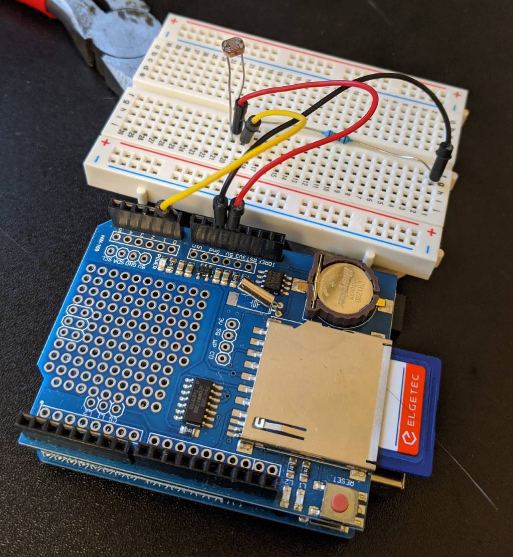
The shield that I'm using solder pads for mounting components onto but I wasn't brave enough for that, so I've been using the pass-through pins and connecting them to the bread board that came with my starter kit.
When it's not connected to a power supply, it looks a bit like this:
The code to read the light level value looks like this (while running this code, try slowly moving your hand closer and further from covering the sensor to see the value change when it's read each second) -
void setup() {
  Serial.begin(9600);
}

void loop() {
  Serial.print("Light level reading: ");
  Serial.print(analogRead(0));
  Serial.println();

  delay(1000);
}
In an effort to start putting all of this together into a more robust package, I picked up a pack of self-adhesive felt pads from the supermarket and stuck them to appropriate points under the breadboard -
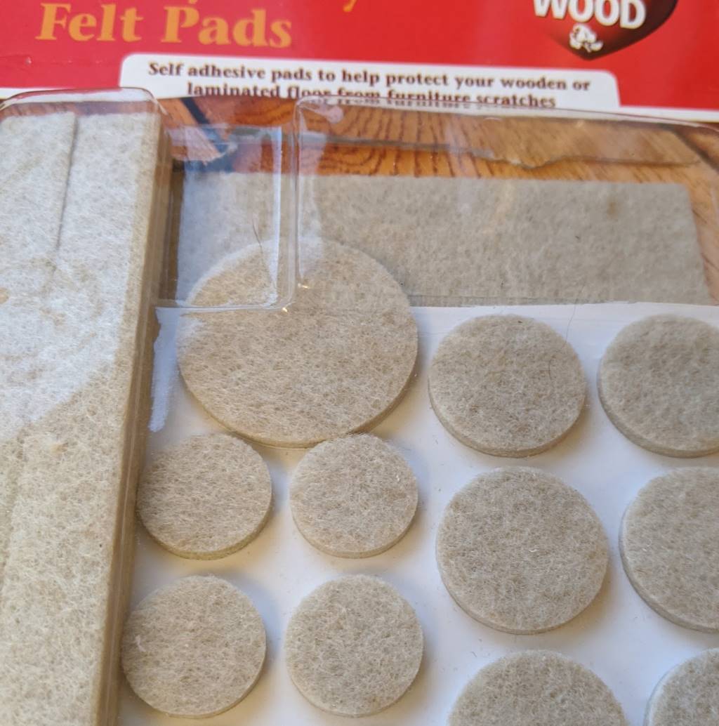
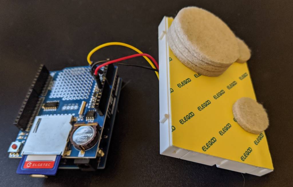
.. and then I secured it all together with an elastic band:
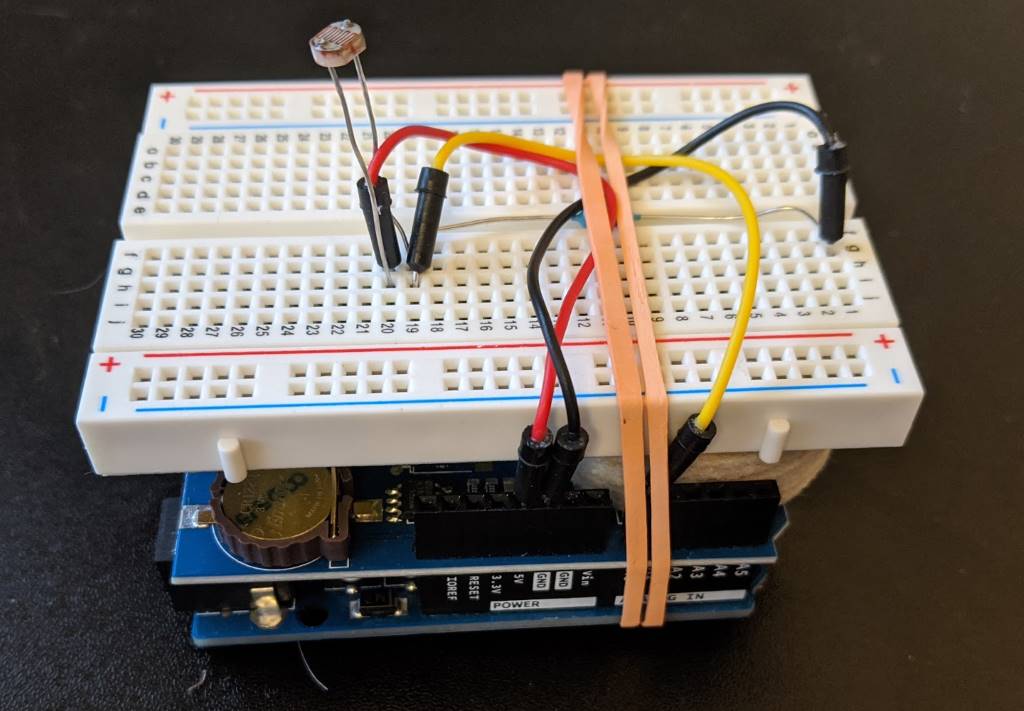
Step 5: Sleeping when not busy
In my ideal dream world, I would be able to leave my light level monitoring box outside for a few months. As I explained earlier, due to the direction that my garden faces, the hours at which the sun hits it fully varies by several hours depending upon the time of year. However, NO battery is going to last forever and even with this 4.5Ah battery that is at a 6V output (which is only a small jump down to regulate to 5V), the time that it can keep things running is limited.
Note: Recharging via a solar panel sounds interesting but it's definitely a future iteration possibility at this point!
There are, however, some things that can be done to eke out the duration of the battery by reducing the power usage of the board. There are ways to put the board into a "power down" state where it will do less - its timers will stop and its CPU can have a rest. There are tutorials out there about how to put it into this mode and have it only wake up on an "interrupt", which can be an external circuit setting an input pin (maybe somehow using the RTC on the shield I'm using) or using something called the "Watchdog Timer" that stays running on the Arduino even when it's in power down mode.
I read a lot of posts and tutorials on this and I really struggled to get it to work. Until, finally, I came across this one: Arduino Sleep Modes and How to use them to Save the Power. It explains in a clear table the difference between the different power-reduced modes (idle, power-save, power-down, etc..) and it recommends a library called "Low-Power" that takes all of the hard work out of it.
Whereas other tutorials talked about calling "sleep_enable()" and "set_sleep_mode(..)" functions and then using "attachInterrupt(..)" and adding some magic method to then undo all of those things, this library allows you to write a one-liner as follows:
LowPower.powerDown(SLEEP_8S, ADC_OFF, BOD_OFF);
This will cause the board to go into its most power-saving mode for eight seconds (which is the longest that's possible when relying upon its internal Watchdog Timer to wake it up).
No muss, no fuss.
I haven't measured yet how long that my complete device can sit outside in its waterproof box on a single charge of a battery but I'm confident that it's definitely measured in days, not hours - and that was before introducing this "LowPower.powerDown(..)" call.
Since I only want a reading every 30-60s, I call "LowPower.powerDown(..)" in a loop so that there are several 8s power down delays. While I haven't confirmed this yet, I would be astonished if it didn't last at least a week out there on one charge. And if I have to bring it in some nights (when it's dark and I don't care about light measurements) to charge it, then that's fine by me (though I'd like to be as infrequently as possible).
Gotcha Seven: When entering power-down mode, if you are connected to the USB port in order to use the Serial Monitor to watch what's going on, ensure that you call "Serial.flush()" before entering power-down, otherwise the message might get buffered up and not fully sent through the serial connection before the board takes a nap.
Step 6: Preparing for the outdoors (in the British weather!)
I always associate the brand "Tupperware" as being a very British thing - it's what we get packed lunches put into and what we get takeaway curries in. At least, I think that it is - maybe it's like "hoover", where everyone uses the phrase "hoover" when they mean their generic vacuum cleaner. Regardless the origin, this seemed like the simplest way to make my device waterproof. The containers are not completely transparent but they shouldn't make a significant impact on the light levels being recorded by the photo-resistor because they're also far from opaque. And these containers are sealable, waterproof and come in all shapes and sizes!
I took my elastic-band-wrapped "stack" of Arduino-plus-shield-plus-breadboard and connected it to the battery -
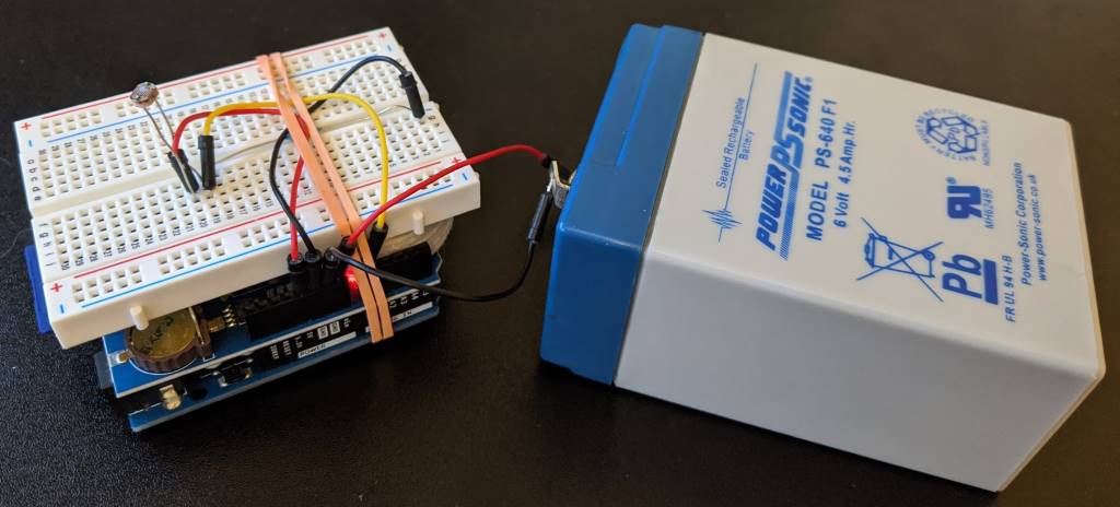
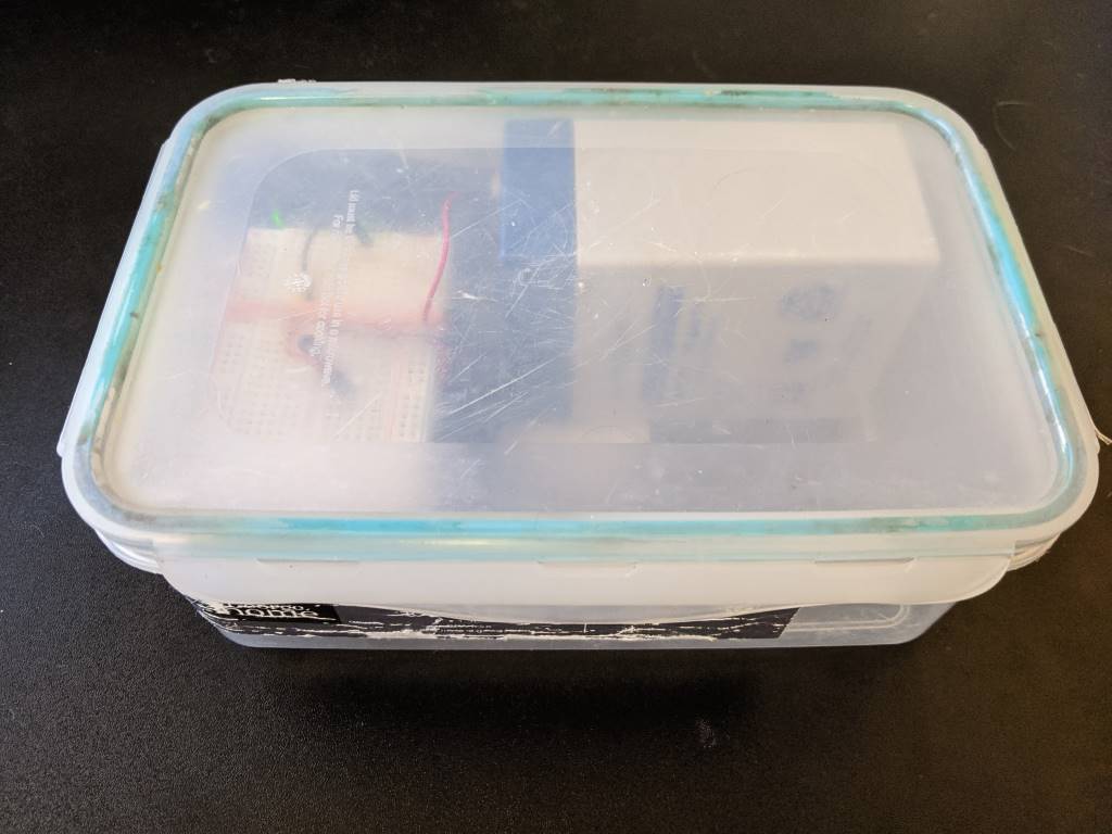
.. and put in a plastic box. By turning the battery so that it was length-side-up, it was quite a snug fit and meant that the battery wouldn't slide around inside the box. There wasn't a lot of space for the stack to move around and so it seemed like quite a secure arrangement:
Step 7: The final code
So far, each code sample has demonstrated aspects of what I want to do but now it's time to bring it all fully together.
In trying to write the following code, I was reminded how much I've taken for granted in C# (and other higher level languages) with their string handling! I tried a little C and C++ maaaaany years ago and so writing Arduino code was a bit of a throwback for me - at first, I was trying to make a char array for a filename and I set the length of the array to be the number of characters that were required for the filename.. silly me, I had forgotten that C strings need to be null-terminated and so you need an extra zero character at the end in order for things to work properly! Failing to do so would not result in a compile or run time error, it would just mean that the files weren't written properly. Oh, how I've been spoilt! But, on the other hand, it also feels kinda good being this close to the "bare metal" :)
The following sketch will record the light level about twice a minute to a file on the SD card where the filename is based upon the current date (as maintained by the RTC module and its CR1220 battery) -
#include <Wire.h>
#include <SdFat.h>    // https://github.com/greiman/SdFat
#include <RTClib.h>   // https://github.com/adafruit/RTClib
#include <LowPower.h> // https://github.com/rocketscream/Low-Power

// chipSelect = 10 according to "Item description" section of
// https://www.play-zone.ch/de/dk-data-logging-shield-v1-0.html
#define SD_CHIP_SELECT 10

RTC_DS1307 rtc;

void setup() {
  // The clock won't work with this (thanks https://arduino.stackexchange.com/a/44305!)
  Wire.begin();

  bool rtcWasAlreadyConfigured;
  if (rtc.isrunning()) {
    rtcWasAlreadyConfigured = true;
  }
  else {
    rtc.adjust(DateTime(__DATE__, __TIME__));
    rtcWasAlreadyConfigured = false;
  }

  Serial.begin(9600);

  if (rtcWasAlreadyConfigured) {
    Serial.println("setup: RTC is already running");
  }
  else {
    Serial.println("setup: RTC was not running, so it was set to the time of compilation");
  }
}

void loop() {
  // Character arrays need to be long enough to store the number of "real" characters plus the
  // null terminator
  char filename[13]; // yyyyMMdd.txt = 12 chars + 1 null
  char timestamp[9]; // 00:00:00     =  8 chars + 1 null
  DateTime now = rtc.now();
  snprintf(filename, sizeof(filename), "%04u%02u%02u.txt", now.year(), now.month(), now.day());
  snprintf(timestamp, sizeof(timestamp), "%02u:%02u:%02u", now.hour(), now.minute(), now.second());

  int sensorValue = analogRead(0);

  Serial.print(filename);
  Serial.print(" ");
  Serial.print(timestamp);
  Serial.print(" ");
  Serial.println(sensorValue);

  SdFat sd;
  if (!sd.begin(SD_CHIP_SELECT, SPI_HALF_SPEED)) {
    Serial.println("ERROR: sd.begin() failed");
  }
  else {
    SdFile file;
    if (!file.open(filename, O_WRITE | O_APPEND | O_CREAT)) {
      Serial.println("ERROR: file.open() failed - unable to write");
    }
    else {
      file.print(timestamp);
      file.print(" Sensor value: ");
      file.println(sensorValue);
      file.close();
    }
  }

  Serial.flush(); // Ensure we finish sending serial messages before going to sleep

  // 4x 8s is close enough to a reading every 30s, which gives me plenty of data
  // - Using this instead of "delay" should mean that the battery will power the device for longer
  for (int i = 0; i < 3; i++) {
    LowPower.powerDown(SLEEP_8S, ADC_OFF, BOD_OFF);
  }
}
At the moment, I'm bringing the box inside each night and then disconnecting the battery, pulling out the card and looking at the values recorded in the file to see if it's clear when the sun was fully hitting the table that I had placed the box on.
I've only started doing this in the last couple of days and each day has been rather grey and so there haven't been any sunny periods so that I can confirm that the readings clearly distinguish between "regular daylight" and "sun directly on the table". Once I get some sun again, I'll be able to get a better idea - and if I can't distinguish well enough then I'll adjust the pull-down resistor that splits the voltage with the LDR and keep experimenting!
When I'm happy with the configuration, then I'll start experimenting with leaving the box outside for longer to see how long this battery can last in conjunction with the "LowPower.powerDown(..)" calls. One obvious optimisation for my use case would be to continue keeping it in power-down mode between the hours of 10pm and 8am - partly because I know that it will definitely be dark after 10pm and partly because I am not a morning person and so would not want to be outside before 8am, even if it was streaming with light (which it wouldn't be due to when my yard actually gets direct sunlight).
Gotcha Eight: The RTC has no awareness of daylight savings time and so I'll need to take this into account when the clocks change in the UK. I'll worry about this another day!
Step 8: Draw some graphs (one day)
As you can tell from the above, I'm still very much in the early phases of gathering data. But, at some point, I'm going to have to use this data to predict when the yard will get sun for future dates - once I've got a few months of data for different times of year, hopefully I'll be able to do so!
I foresee a little bit of data-reading and Excel-graph-drawing in my future! There's just something about seeing results on a graph that make everything feel so much more real. As much as I'd like to be able to stare at 1000s of numbers and read them like the Matrix, seeing trends and curves plotted out just feels so much more satisfying and definitive. Maybe there will be a follow-up post with the results, though I feel that they would be much more personal and less useful to the general populace than even my standard level of esoteric and niche blog posts! Maybe there are some graphs in my Twitter stream's future!
On the other hand.. if I learn any more power-saving techniques or have any follow-up information about how long these rechargeable torch-or-remote-control batteries last then maybe that will be grounds for a follow-up!
In the meantime, I hope you've enjoyed this little journey - and if you've tried to do anything similar with these cheap Deek Robot boards, then maybe the code samples here have been of use to you. I hope so! (Because, goodness knows, feeling like a beginner again and getting onto those new forums has been quite an experience!)
Posted at 21:34
How are barcodes read?? (Library-less image processing in C#)
I've been using MyFitnessPal and it has the facility to load nutrition information by scanning the barcode on the product. I can guess how the retrieval works once the barcode number is obtained (a big database somewhere) but it struck me that I had no idea how the reading of the barcode itself worked and.. well, I'm curious and enjoy the opportunity to learn something new to me by writing the code to do it. I do enjoy being able to look up (almost) anything on the internet to find out how it works!
(For anyone who wants to either play along but not copy-paste the code themselves or for anyone who wants to jump to the end result, I've put the code - along with the example image I've used in this post - up on a GitHub repo)
The plan of attack
There are two steps required here:
- Read image and try to identify areas that look like barcodes
- Try to extract numbers from the looks-like-a-barcode regions
As with anything, these steps may be broken down into smaller tasks. The first step can be done like this:
- Barcodes are black and white regions that have content that has steep "gradients" in image intensity horizontally (where there is a change from a black bar to a white space) and little change in intensity vertically (as each bar is a vertical line), so first we greyscale the image and then generate horizontal and vertical intensity gradients values for each point in the image and combine the values by subtracting vertical gradient from horizontal gradient
- These values are normalised so that they are all on the scale zero to one - this data could be portrayed as another greyscale image where the brightest parts are most likely to be within barcodes
- These values are then "spread out" or "blurred" and then a threshold value is applied where every value about it is changed into a 1 and every value below it a 0
- This "mask" (where every value is a 0 or 1) should have identified many of the pixels within the barcodes and we want to group these pixels into distinct objects
- There is a chance, though, that there could be gaps between bars that mean that a single barcode is spread across multiple masked-out objects and we need to try to piece them back together into one area (since the bars are tall and narrow, this may be done by considering a square area over every object and then combining objects whose squared areas overlap into one)
- This process will result in a list of areas that may be barcodes - any that are taller than they are wide are ignored (because barcode regions are always wider than they are tall)
The second step can be broken down into:
- Take the maybe-barcode region of the image, greyscale it and then turn into a mask by setting any pixel with an intensity less than a particular threshold to zero and otherwise to one
- Take a horizontal slice across the image region - all of the pixels on the first row of the image - and change the zero-or-one raw data into a list of line lengths where a new line starts at any transition from zero-to-one or one-to-zero (so "01001000110" becomes "1,1,2,1,3,2,1" because there is 1x zero and then 1x one and then 2x zero and then 1x one, etc..)
- These line lengths should correspond to bar sizes (and space-between-bar sizes) if we've found a barcode - so run the values through the magic barcode bar-size-reading algorithm (see section 2.1 in https://www.ncbi.nlm.nih.gov/pmc/articles/PMC2859730/) and if we get a number (and the checksum is correct) then we're done, hurrah!
- If we couldn't get a number from this horizontal slice then move one pixel down and go back around
- If it was not possible to extract a number from any of the slices through the image region then it's either not a barcode or it's somehow so distorted in the image that we can't read it
This approach is fairly resilient to changes in lighting and orientation because the barcode regions are still likely to have the highest horizontal intensity gradient whether the image is dark or light (and even if part of the image is light and part of it is dark) and the barcode-reading algorithm works on ratios of bar/space-between-bar widths and these remain constant if the image is rotated.
(Some of the techniques are similar to things that I did in my Face or no face (finding faces in photos using C# and Accord.NET) and so I'll be using some of the same code shortly that I described then)
Identifying maybe-barcode images
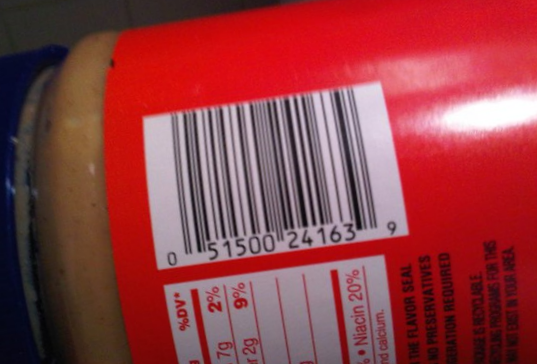
Let's this image as an example to work with (peanut butter.. I do love peanut butter) -
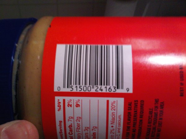
Before looking at any code, let's visualise the process.
We're going to consider horizontal and vertical gradient intensity maps - at every point in the image we either look to the pixels to the left and to the right (for the horizontal gradient) or we look at the pixels above and below (for the vertical gradient) and the larger the change, the brighter the pixel in the gradient intensity map
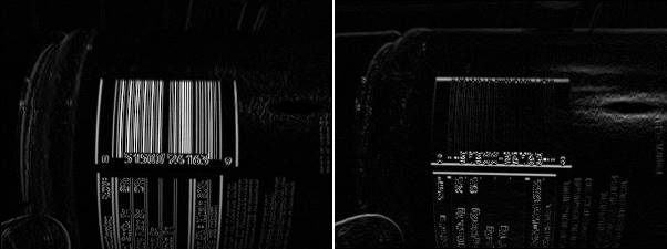
And when they're combined by subtracting the vertical gradient at each point from the horizontal gradient, it looks lke this:
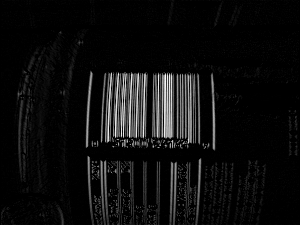
If this image is blurred then we get this:

.. and if we create a binary mask by saying "normalise the intensity values so that their range goes from zero (for the darkest pixel) to one (for the brightest) and then set any pixels that are in the bottom third in terms of intensity to 0 and set the rest to 1" then we get this:

If each distinct area (where an "area" means "a group of pixels that are connected") is identified and squares overlaid and centered around the areas then we see this:
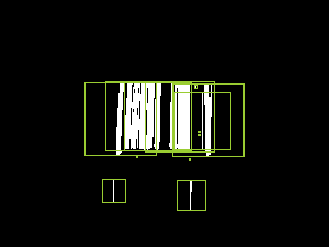
.. and if the areas whose bounding squares overlap are combined and then cropped around the white pixels then we end up with this:
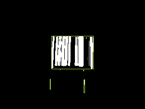
This has identified the area around the barcode and also two tiny other areas - when we come to trying to read barcode numbers out of these, the tiny regions will result in no value while the area around the genuine barcode content should result in a number successfully being read. But I'm getting ahead of myself.. let's look at the code required to perform the above transformations.
I'm going to start with a DataRectangle for performing transformations -
public static class DataRectangle
{
    public static DataRectangle<T> For<T>(T[,] values) => new DataRectangle<T>(values);
}

public sealed class DataRectangle<T>
{
    private readonly T[,] _protectedValues;
    public DataRectangle(T[,] values) : this(values, isolationCopyMayBeBypassed: false) { }
    private DataRectangle(T[,] values, bool isolationCopyMayBeBypassed)
    {
        if ((values.GetLowerBound(0) != 0) || (values.GetLowerBound(1) != 0))
            throw new ArgumentException("Both dimensions must have lower bound zero");
        var arrayWidth = values.GetUpperBound(0) + 1;
        var arrayHeight = values.GetUpperBound(1) + 1;
        if ((arrayWidth == 0) || (arrayHeight == 0))
            throw new ArgumentException("zero element arrays are not supported");

        Width = arrayWidth;
        Height = arrayHeight;

        if (isolationCopyMayBeBypassed)
            _protectedValues = values;
        else
        {
            _protectedValues = new T[Width, Height];
            Array.Copy(values, _protectedValues, Width * Height);
        }
    }

    /// <summary>
    /// This will always be greater than zero
    /// </summary>
    public int Width { get; }

    /// <summary>
    /// This will always be greater than zero
    /// </summary>
    public int Height { get; }

    public T this[int x, int y]
    {
        get
        {
            if ((x < 0) || (x >= Width))
                throw new ArgumentOutOfRangeException(nameof(x));
            if ((y < 0) || (y >= Height))
                throw new ArgumentOutOfRangeException(nameof(y));
            return _protectedValues[x, y];
        }
    }

    public IEnumerable<Tuple<Point, T>> Enumerate(Func<Point, T, bool>? optionalFilter = null)
    {
        for (var x = 0; x < Width; x++)
        {
            for (var y = 0; y < Height; y++)
            {
                var value = _protectedValues[x, y];
                var point = new Point(x, y);
                if (optionalFilter?.Invoke(point, value) ?? true)
                    yield return Tuple.Create(point, value);
            }
        }
    }

    public DataRectangle<TResult> Transform<TResult>(Func<T, TResult> transformer)
    {
        return Transform((value, coordinates) => transformer(value));
    }

    public DataRectangle<TResult> Transform<TResult>(Func<T, Point, TResult> transformer)
    {
        var transformed = new TResult[Width, Height];
        for (var x = 0; x < Width; x++)
        {
            for (var y = 0; y < Height; y++)
                transformed[x, y] = transformer(_protectedValues[x, y], new Point(x, y));
        }
        return new DataRectangle<TResult>(transformed, isolationCopyMayBeBypassed: true);
    }
}
And then I'm going to add a way to load image data into this structure -
public static class BitmapExtensions
{
    /// <summary>
    /// This will return values in the range 0-255 (inclusive)
    /// </summary>
    // Based on http://stackoverflow.com/a/4748383/3813189
    public static DataRectangle<double> GetGreyscale(this Bitmap image)
    {
        var values = new double[image.Width, image.Height];
        var data = image.LockBits(
            new Rectangle(0, 0, image.Width, image.Height),
            ImageLockMode.ReadOnly,
            PixelFormat.Format24bppRgb
        );
        try
        {
            var pixelData = new Byte[data.Stride];
            for (var lineIndex = 0; lineIndex < data.Height; lineIndex++)
            {
                Marshal.Copy(
                    source: data.Scan0 + (lineIndex * data.Stride),
                    destination: pixelData,
                    startIndex: 0,
                    length: data.Stride
                );
                for (var pixelOffset = 0; pixelOffset < data.Width; pixelOffset++)
                {
                    // Note: PixelFormat.Format24bppRgb means the data is stored in memory as BGR
                    const int PixelWidth = 3;
                    var r = pixelData[pixelOffset * PixelWidth + 2];
                    var g = pixelData[pixelOffset * PixelWidth + 1];
                    var b = pixelData[pixelOffset * PixelWidth];
                    values[pixelOffset, lineIndex] = (0.2989 * r) + (0.5870 * g) + (0.1140 * b);
                }
            }
        }
        finally
        {
            image.UnlockBits(data);
        }
        return DataRectangle.For(values);
    }
}
With these classes, we can load an image and calculate the combined horizontal-gradient-minus-vertical-gradient value like this:
private static IEnumerable<Rectangle> GetPossibleBarcodeAreasForBitmap(Bitmap image)
{
    var greyScaleImageData = image.GetGreyscale();
    var combinedGradients = greyScaleImageData.Transform((intensity, pos) =>
    {
        // Consider gradients to be zero at the edges of the image because there aren't pixels
        // both left/right or above/below and so it's not possible to calculate a real value
        var horizontalChange = (pos.X == 0) || (pos.X == greyScaleImageData.Width - 1)
            ? 0
            : greyScaleImageData[pos.X + 1, pos.Y] - greyScaleImageData[pos.X - 1, pos.Y];
        var verticalChange = (pos.Y == 0) || (pos.Y == greyScaleImageData.Height - 1)
            ? 0
            : greyScaleImageData[pos.X, pos.Y + 1] - greyScaleImageData[pos.X, pos.Y - 1];
        return Math.Max(0, Math.Abs(horizontalChange) - Math.Abs(verticalChange));
    });

    // .. more will go here soon
}
Before jumping straight into the image analysis, though, it's worth resizing the source image if it's large. Since this stage of the processing is looking for areas that look approximately like barcodes, we don't require a lot of granularity - I'm envisaging (as with the MyFitnessPal use case) source images where the barcode takes up a significant space in the image and is roughly aligned with the view port* and so resizing the image such that the largest side is 300px should work well. If you wanted to scan an image where there were many barcodes to process (or even where there was only one but it was very small) then you might want to allow larger inputs than this - the more data that there is, though, the more work that must be done and the slower that the processing will be!
* (The barcode has to be roughly aligned with the viewport because the approaching of looking for areas with large horizontal variance in intensity with minor vertical variance would not work - as we'll see later, though, there is considerable margin for error in this approach and perfect alignment is not required)
A naive approach to this would be force the image so that its largest side is 300px, regardless of what it was originally. However, this is unnecessary if the largest side is already less than 300px (scaling it up will actually give us more work to do) and if the largest side is not much more than 300px then it's probably not worth doing either - scaling it down may make any barcodes areas fuzzy and risk reducing the effectiveness of the processing while not actually reducing the required work. So I'm going to say that if the largest side of the image is 450px or larger than resize it so that its largest side is 300px and do nothing otherwise. To achieve that, we need a method like this:
private static DataRectangle<double> GetGreyscaleData(
    Bitmap image,
    int resizeIfLargestSideGreaterThan,
    int resizeTo)
{
    var largestSide = Math.Max(image.Width, image.Height);
    if (largestSide <= resizeIfLargestSideGreaterThan)
        return image.GetGreyscale();

    int width, height;
    if (image.Width > image.Height)
    {
        width = resizeTo;
        height = (int)(((double)image.Height / image.Width) * width);
    }
    else
    {
        height = resizeTo;
        width = (int)(((double)image.Width / image.Height) * height);
    }
    using var resizedImage = new Bitmap(image, width, height);
    return resizedImage.GetGreyscale();
}
The next steps are to "normalise" the combined intensity variance values so that they fit the range zero-to-one, to "blur" this data and to then create a binary mask where the brighter pixels get set to one and the darker pixels get set to zero. In other words, to extend the code earlier (that calculated the intensity variance values) like this:
private static IEnumerable<Rectangle> GetPossibleBarcodeAreasForBitmap(Bitmap image)
{
    var greyScaleImageData = GetGreyscaleData(
        image,
        resizeIfLargestSideGreaterThan: 450,
        resizeTo: 300
    );
    var combinedGradients = greyScaleImageData.Transform((intensity, pos) =>
    {
        // Consider gradients to be zero at the edges of the image because there aren't pixels
        // both left/right or above/below and so it's not possible to calculate a real value
        var horizontalChange = (pos.X == 0) || (pos.X == greyScaleImageData.Width - 1)
            ? 0
            : greyScaleImageData[pos.X + 1, pos.Y] - greyScaleImageData[pos.X - 1, pos.Y];
        var verticalChange = (pos.Y == 0) || (pos.Y == greyScaleImageData.Height - 1)
            ? 0
            : greyScaleImageData[pos.X, pos.Y + 1] - greyScaleImageData[pos.X, pos.Y - 1];
        return Math.Max(0, Math.Abs(horizontalChange) - Math.Abs(verticalChange));
    });

    const int maxRadiusForGradientBlurring = 2;
    const double thresholdForMaskingGradients = 1d / 3;

    var mask = Blur(Normalise(combinedGradients), maxRadiusForGradientBlurring)
        .Transform(value => (value >= thresholdForMaskingGradients));

    // .. more will go here soon
}
To do that we, need a "Normalise" method - which is simple:
private static DataRectangle<double> Normalise(DataRectangle<double> values)
{
    var max = values.Enumerate().Max(pointAndValue => pointAndValue.Item2);
    return (max == 0)
        ? values
        : values.Transform(value => (value / max));
}
.. and a "Blur" method - which is a little less simple but hopefully still easy enough to follow (for every point, look at the points around it and take an average of all of them; it just looks for a square area, which is fine for small "maxRadius" values but which might be better implemented as a circular area if large "maxRadius" values might be needed, which they aren't in this code):
private static DataRectangle<double> Blur(DataRectangle<double> values, int maxRadius)
{
    return values.Transform((value, point) =>
    {
        var valuesInArea = new List<double>();
        for (var x = -maxRadius; x <= maxRadius; x++)
        {
            for (var y = -maxRadius; y <= maxRadius; y++)
            {
                var newPoint = new Point(point.X + x, point.Y + y);
                if ((newPoint.X < 0) || (newPoint.Y < 0)
                || (newPoint.X >= values.Width) || (newPoint.Y >= values.Height))
                    continue;
                valuesInArea.Add(values[newPoint.X, newPoint.Y]);
            }
        }
        return valuesInArea.Average();
    });
}
This gets us to this point:

.. which feels like good progress!
Now we need to try to identify distinct "islands" of pixels where each "island" or "object" is a set of points that are within a single connected area. A straightforward way to do that is to look at every point in the mask that is set to 1 and either:
- Perform a pixel-style "flood fill" starting at this point in order to find other points in an object
- If this pixel has already been included in such a fill operation, do nothing (because it's already been accounted for)
This was made easier for me by reading the article Flood Fill algorithm (using C#.Net)..
private static IEnumerable<IEnumerable<Point>> GetDistinctObjects(DataRectangle<bool> mask)
{
    // Flood fill areas in the looks-like-bar-code mask to create distinct areas
    var allPoints = new HashSet<Point>(
        mask.Enumerate(optionalFilter: (point, isMasked) => isMasked).Select(point => point.Item1)
    );
    while (allPoints.Any())
    {
        var currentPoint = allPoints.First();
        var pointsInObject = GetPointsInObject(currentPoint).ToArray();
        foreach (var point in pointsInObject)
            allPoints.Remove(point);
        yield return pointsInObject;
    }

    // Inspired by code at
    // https://simpledevcode.wordpress.com/2015/12/29/flood-fill-algorithm-using-c-net/
    IEnumerable<Point> GetPointsInObject(Point startAt)
    {
        var pixels = new Stack<Point>();
        pixels.Push(startAt);

        var valueAtOriginPoint = mask[startAt.X, startAt.Y];
        var filledPixels = new HashSet<Point>();
        while (pixels.Count > 0)
        {
            var currentPoint = pixels.Pop();
            if ((currentPoint.X < 0) || (currentPoint.X >= mask.Width)
            || (currentPoint.Y < 0) || (currentPoint.Y >= mask.Height))
                continue;

            if ((mask[currentPoint.X, currentPoint.Y] == valueAtOriginPoint)
            && !filledPixels.Contains(currentPoint))
            {
                filledPixels.Add(new Point(currentPoint.X, currentPoint.Y));
                pixels.Push(new Point(currentPoint.X - 1, currentPoint.Y));
                pixels.Push(new Point(currentPoint.X + 1, currentPoint.Y));
                pixels.Push(new Point(currentPoint.X, currentPoint.Y - 1));
                pixels.Push(new Point(currentPoint.X, currentPoint.Y + 1));
            }
        }
        return filledPixels;
    }
}
The problem is that, even with the blurring we performed, there will likely be some groups of distinct objects that are actually part of a single barcode. These areas need to be joined together. It's quite possible for there to be relatively large gaps in the middle of barcodes (there is in the example that we've been looking at) and so we might not easily be able to just take the distinct objects that we've got and join together areas that seem "close enough".
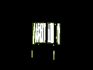
On the basis that individual bars in a barcode are tall compared to the largest possible width that any of them can be (which I'll go into more detail about later on), it seems like a reasonable idea to take any areas that are taller than they are wide and expand their width until they become square. That would give us this:

We'd then work out which of these "squared off" rectangles overlap (if any) and replace overlapping rectangles with rectangles that cover their combined areas, which would look like this:
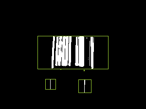
The only problem with this is that the combined rectangles extend too far to the left and right of the areas, so we need to trim them down. The will be fairly straightforward because we have the information about what distinct objects there are and each object is just a list of points - so we work out which objects have points within each of the combined bounding areas and then we work out which out of all of the objects for each combined area has the smallest "x" value and smallest "y" value and which have the largest values. That way, we can change the combined bounding areas to only cover actual barcode pixels. Which would leave us with this:

That might sound like a lot of complicated work but if we take a bit of a brute force* approach to it then it can be expressed like this:
private static IEnumerable<Rectangle> GetOverlappingObjectBounds(
    IEnumerable<IEnumerable<Point>> objects)
{
    // Translate each "object" (a list of connected points) into a bounding box (squared off if
    // it was taller than it was wide)
    var squaredOffBoundedObjects = new HashSet<Rectangle>(
        objects.Select((points, index) =>
        {
            var bounds = Rectangle.FromLTRB(
                points.Min(p => p.X),
                points.Min(p => p.Y),
                points.Max(p => p.X) + 1,
                points.Max(p => p.Y) + 1
            );
            if (bounds.Height > bounds.Width)
                bounds.Inflate((bounds.Height - bounds.Width) / 2, 0);
            return bounds;
        })
    );

    // Loop over the boundedObjects and reduce the collection by merging any two rectangles
    // that overlap and then starting again until there are no more bounds merges to perform
    while (true)
    {
        var combinedOverlappingAreas = false;
        foreach (var bounds in squaredOffBoundedObjects)
        {
            foreach (var otherBounds in squaredOffBoundedObjects)
            {
                if (otherBounds == bounds)
                    continue;

                if (bounds.IntersectsWith(otherBounds))
                {
                    squaredOffBoundedObjects.Remove(bounds);
                    squaredOffBoundedObjects.Remove(otherBounds);
                    squaredOffBoundedObjects.Add(Rectangle.FromLTRB(
                        Math.Min(bounds.Left, otherBounds.Left),
                        Math.Min(bounds.Top, otherBounds.Top),
                        Math.Max(bounds.Right, otherBounds.Right),
                        Math.Max(bounds.Bottom, otherBounds.Bottom)
                    ));
                    combinedOverlappingAreas = true;
                    break;
                }
            }
            if (combinedOverlappingAreas)
                break;
        }
        if (!combinedOverlappingAreas)
            break;
    }

    return squaredOffBoundedObjects.Select(bounds =>
    {
        var allPointsWithinBounds = objects
            .Where(points => points.Any(point => bounds.Contains(point)))
            .SelectMany(points => points)
            .ToArray(); // Don't re-evaluate in the four accesses below
        return Rectangle.FromLTRB(
            left: allPointsWithinBounds.Min(p => p.X),
            right: allPointsWithinBounds.Max(p => p.X) + 1,
            top: allPointsWithinBounds.Min(p => p.Y),
            bottom: allPointsWithinBounds.Max(p => p.Y) + 1
        );
    });
}
* (There are definitely more efficient ways that this could be done but since we're only looking at 300px images then we're not likely to end up with huge amounts of data to deal with)
To complete the process, we need to do three more things:
- Since barcodes are wider than they are tall, we can discard any regions that don't fit this shape (of which there are two in the example image)
- The remaining regions are expanded a little across so that they more clearly surround the barcode region, rather than being butted right up to it (this will make the barcode reading process a little easier)
- As the regions that have been identified may well be on a resized version of the source image, they may need to scaled up so that they correctly apply to the source
To do that, we'll start from this code that we saw earlier:
var mask = Blur(Normalise(combinedGradients), maxRadiusForGradientBlurring)
    .Transform(value => (value >= thresholdForMaskingGradients));
.. and expand it like so (removing the "// .. more will go here soon" comment), using the methods above:
// Determine how much the image was scaled down (if it had to be scaled down at all)
// by comparing the width of the potentially-scaled-down data to the source image
var reducedImageSideBy = (double)image.Width / greyScaleImageData.Width;

var mask = Blur(Normalise(combinedGradients), maxRadiusForGradientBlurring)
    .Transform(value => (value >= thresholdForMaskingGradients));

return GetOverlappingObjectBounds(GetDistinctObjects(mask))
    .Where(boundedObject => boundedObject.Width > boundedObject.Height)
    .Select(boundedObject =>
    {
        var expandedBounds = boundedObject;
        expandedBounds.Inflate(width: expandedBounds.Width / 10, height: 0);
        expandedBounds.Intersect(
            Rectangle.FromLTRB(0, 0, greyScaleImageData.Width, greyScaleImageData.Height)
        );
        return new Rectangle(
            x: (int)(expandedBounds.X * reducedImageSideBy),
            y: (int)(expandedBounds.Y * reducedImageSideBy),
            width: (int)(expandedBounds.Width * reducedImageSideBy),
            height: (int)(expandedBounds.Height * reducedImageSideBy)
        );
    });
The final result is that the barcode has been successfully located on the image - hurrah!
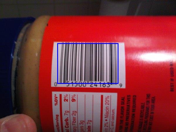
With this information, we should be able to extract regions or "sub images" from the source image and attempt to decipher the barcode value in it (presuming that there IS a bar code in it and we haven't got a false positive match).
As we'll see in a moment, the barcode doesn't have to be perfectly lined up - some rotation is acceptable (depending upon the image, up to around 20 or 30 degrees should be fine). The MyFitnessPal app has a couple of fallbacks that I've noticed, such as being able to read barcodes that are upside down or even back to front (which can happen if a barcode is scanned from the wrong side of a transparent wrapper). While I won't be writing code here for either of those approaches, I'm sure that you could envisage how it could be done - the source image data could be processed as described here and then, if no barcode is read, rotated 180 degrees and re-processed and reversed and re-processed, etc..
How to read a bar code
A barcode is comprised of both black and white bars - so it's not just the black parts that are significant, it is the spaces between them as well.
The format of a barcode is as follows:
- Three single-width bars (a black one, a white one and another black one) that are used to gauge what is considered to be a "single width"
- Information for six numbers then appears, where each number is encoded by a sequence of four bars (white, black, white, black) - particular combinations of bar widths relate to particular digits (see below)
- Another guard section appears with five single width bars (white, black, white, black, white)
- Six more numbers appear (using the same bar-width-combinations encoding as before but the groups of four bars are now black, white, black, white)
- A final guard section of three single width bards (black, white, black)
The numbers are encoded using the following system:
 Digit      Bar widths

   0        3, 2, 1, 1
   1        2, 2, 2, 1
   2        2, 1, 2, 2
   3        1, 4, 1, 1
   4        1, 1, 3, 2
   5        1, 2, 3, 1
   6        1, 1, 1, 4
   7        1, 3, 1, 2
   8        1, 2, 1, 3
   9        3, 1, 1, 2
(Note that every combination of values totals 7 when they added up - this is very helpful later!)
To see what that looks like in the real world, here's a slice of that barcode from the jar of peanut butter with each section and each numeric value identified:
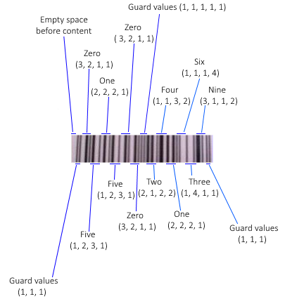
(I should point out that the article How does a barcode work? was extremely helpful in the research I did for this post and I'm very grateful to the author for having written it in such an approachable manner!)
Any combination of bar widths that is not found in the table is considered to be invalid. On the one hand, you might think that this a potential loss; the format could support more combinations of bar widths to encode more values and then more data could be packed into the same space. There is an advantage, however, to having relatively few valid combinations of bar widths - it makes easier to tell whether the information being read appears to be correct. If a combination is encountered that seems incorrect then the read attempt should be aborted and retried. The format has existed for decades and it would make sense, bearing that in mind, to prioritise making it easier for the hardware to read rather prioritising trying to cram as much data in there as possible. There is also a checksum included in the numerical data to try to catch any "misreads" but when working with low resolutions or hardware with little computing power, the easier that it is to bail out of a scan and to retry the better.
The way to tackle the reading is to:
- Convert the sub image to greyscale
- Create a binary mask so that the darker pixels become 0 and the lighter ones become 1
- Take a single line across the area
- Change the individual 1s and 0s into lengths of continuous "runs" of values
- eg. 0001100 would become 3, 2, 2 because there are three 0s then two 1s and then two 0s
- These runs of values will represent the different sized (black and white) bars that were encountered
- For a larger image, each run length will be longer than for a small image but that won't matter because when we encounter runs of four bar length values that we think should be interpreted as a single digit, we'll do some dividing to try to guess the average size of a single width bar
- Take these runs of values, skip through the expected guard regions and try to interpret each set of four bars that is thought to represent a digit of the bar code as that digit
- If successful then perform a checksum calculation on the output and return the value ass a success if it meets expectations
- If the line couldn't be interpreted as a barcode or the checksum calculation fails then take the next line down and go back to step 4
- If there are no more lines to attempt then a barcode could not be identified in the image
This processing is fairly light computationally and so there is no need to resize the "may be a barcode" image region before attempting the work. In fact, it's beneficial to not shrink it as shrinking it will likely make the barcode section fuzzier and that makes the above steps less likely to work - the ideal case for creating a binary mask is where there is no significant "seepage" of pixel intensity between the black bar areas and the white bar areas. That's not to say that the images have to be crystal clear or perfectly aligned with the camera because the redundancy built into the format works in our favour here - if one line across the image can't be read because it's fuzzy then there's a good chance that one of the other lines will be legible.
60 length values is the precise number that we expect to find - there is expected to be some blank space before the barcode starts (1) and then a guard section of three single-width lines that we use to gauge bar width (3) and then six numbers that are encoded in four bars each (6x4=24) and then a guard section of five single-width lines (5) and then six numbers (6x4=24) and then a final guard region of three single-width bars, giving 1+3+24+5+24+3=60.
There will likely be another section of blank content after the barcode that we ignore
If we don't want to validate the final guard region then we can work with a barcode image where some of the end of cut off, so long as the data for the 12 digits is there; in this case, 57 lengths if the minimum number that we can accept
Reading the numeric value with code
I'm going to try to present the code in approximately the same order as the steps presented above. So, firstly we need to convert the sub image to greyscale and create a binary mark from it. Then we'll go line by line down the image data and try to read a value. So we'll take this:
public static string? TryToReadBarcodeValue(Bitmap subImage)
{
    const double threshold = 0.5;

     // Black lines are considered 1 and so we set to true if it's a dark pixel (and 0 if light)
    var mask = subImage.GetGreyscale().Transform(intensity => intensity < (256 * threshold));
    for (var y = 0; y < mask.Height; y++)
    {
        var value = TryToReadBarcodeValueFromSingleLine(mask, y);
        if (value is object)
            return value;
    }
    return null;
}
.. and the read-each-slice-of-the-image code looks like this:
private static string? TryToReadBarcodeValueFromSingleLine(
    DataRectangle<bool> barcodeDetails,
    int sliceY)
{
    if ((sliceY < 0) || (sliceY >= barcodeDetails.Height))
        throw new ArgumentOutOfRangeException(nameof(sliceY));

    var lengths = GetBarLengthsFromBarcodeSlice(barcodeDetails, sliceY).ToArray();
    if (lengths.Length < 57)
    {
        // As explained, we'd like 60 bars (which would include the final guard region) but we
        // can still make an attempt with 57 (but no fewer)
        // - There will often be another section of blank content after the barcode that we ignore
        // - If we don't want to validate the final guard region then we can work with a barcode
        //   image where some of the end is cut off, so long as the data for the 12 digits is
        //   there (this will be the case where there are only 57 lengths)
        return null;
    }

    var offset = 0;
    var extractedNumericValues = new List<int>();
    for (var i = 0; i < 14; i++)
    {
        if (i == 0)
        {
            // This should be the first guard region and it should be a pattern of three single-
            // width bars
            offset += 3;
        }
        else if (i == 7)
        {
            // This should be the guard region in the middle of the barcode and it should be a
            // pattern of five single-width bars
            offset += 5;
        }
        else
        {
            var value = TryToGetValueForLengths(
                lengths[offset],
                lengths[offset + 1],
                lengths[offset + 2],
                lengths[offset + 3]
            );
            if (value is null)
                return null;
            extractedNumericValues.Add(value.Value);
            offset += 4;
        }
    }

    // Calculate what the checksum should be based upon the first 11 numbers and ensure that
    // the 12th matches it
    if (extractedNumericValues.Last() != CalculateChecksum(extractedNumericValues.Take(11)))
        return null;

    return string.Join("", extractedNumericValues);
}
With the code below, we find the runs of continuous 0 or 1 lengths that will represent bars are return that list (again, for larger images each run will be longer and for smaller images each run will be shorter but this will be taken care of later) -
private static IEnumerable<int> GetBarLengthsFromBarcodeSlice(
    DataRectangle<bool> barcodeDetails,
    int sliceY)
{
    if ((sliceY < 0) || (sliceY >= barcodeDetails.Height))
        throw new ArgumentOutOfRangeException(nameof(sliceY));

    // Take the horizontal slice of the data
    var values = new List<bool>();
    for (var x = 0; x < barcodeDetails.Width; x++)
        values.Add(barcodeDetails[x, sliceY]);

    // Split the slice into bars - we only care about how long each segment is when they
    // alternate, not whether they're dark bars or light bars
    var segments = new List<Tuple<bool, int>>();
    foreach (var value in values)
    {
        if ((segments.Count == 0) || (segments[^1].Item1 != value))
            segments.Add(Tuple.Create(value, 1));
        else
            segments[^1] = Tuple.Create(value, segments[^1].Item2 + 1);
    }
    if ((segments.Count > 0) && !segments[0].Item1)
    {
        // Remove the white space before the first bar
        segments.RemoveAt(0);
    }
    return segments.Select(segment => segment.Item2);
}
Now we need to implement the "TryToGetValueForLengths" method that "TryToReadBarcodeValueFromSingleLine" calls. This takes four bar lengths that are thought to represent a single digit in the bar code value (they are not part of a guard region or anything like that). It take those four bar lengths and guesses how many pixels across a single bar would be - which is made my simpler by the fact that all of the possible combinations of bar lengths in the lookup chart that we saw earlier add up to 7.
There's a little flexibility introduced here to try to account for a low quality image or if the threshold was a bit strong in the creation of the binary mask; we'll take that calculated expected width of a single bar and tweak it up or down a little if apply that division to the bar lengths means that we made some of the bars too small that they disappeared or too large and it seemed like the total width would be more than seven single estimated-width bars. There's only a little flexibility here because if we fail then we can always try another line of the image! (Or maybe it will turn out that this sub image was a false positive match and there isn't a bar code in it at all).
private static int? TryToGetValueForLengths(int l0, int l1, int l2, int l3)
{
    if (l0 <= 0)
        throw new ArgumentOutOfRangeException(nameof(l0));
    if (l1 <= 0)
        throw new ArgumentOutOfRangeException(nameof(l1));
    if (l2 <= 0)
        throw new ArgumentOutOfRangeException(nameof(l2));
    if (l3 <= 0)
        throw new ArgumentOutOfRangeException(nameof(l3));

    // Take a guess at what the width of a single bar is based upon these four values
    // (the four bars that encode a number should add up to a width of seven)
    var raw = new[] { l0, l1, l2, l3 };
    var singleWidth = raw.Sum() / 7d;
    var adjustment = singleWidth / 10;
    var attemptedSingleWidths = new HashSet<double>();
    while (true)
    {
        var normalised = raw.Select(x => Math.Max(1, (int)Math.Round(x / singleWidth))).ToArray();
        var sum = normalised.Sum();
        if (sum == 7)
            return TryToGetNumericValue(normalised[0], normalised[1], normalised[2], normalised[3]);

        attemptedSingleWidths.Add(singleWidth);
        if (sum > 7)
            singleWidth += adjustment;
        else
            singleWidth -= adjustment;
        if (attemptedSingleWidths.Contains(singleWidth))
        {
            // If we've already tried this width-of-a-single-bar value then give up -
            // it doesn't seem like we can make the input values make sense
            return null;
        }
    }

    static int? TryToGetNumericValue(int i0, int i1, int i2, int i3)
    {
        var lookFor = string.Join("", new[] { i0, i1, i2, i3 });
        var lookup = new[]
        {
            // These values correspond to the lookup chart shown earlier
            "3211", "2221", "2122", "1411", "1132", "1231", "1114", "1312", "1213", "3112"
        };
        for (var i = 0; i < lookup.Length; i++)
        {
            if (lookFor == lookup[i])
                return i;
        }
        return null;
    }
}
Finally we need the CalculateChecksum method (as noted in the code, there's a great explanation of how to do this in wikipedia) -
private static int CalculateChecksum(IEnumerable<int> values)
{
    if (values == null)
        throw new ArgumentNullException(nameof(values));
    if (values.Count() != 11)
        throw new ArgumentException("Should be provided with precisely 11 values");

    // See https://en.wikipedia.org/wiki/Check_digit#UPC
    var checksumTotal = values
        .Select((value, index) => (index % 2 == 0) ? (value * 3) : value)
        .Sum();
    var checksumModulo = checksumTotal % 10;
    if (checksumModulo != 0)
        checksumModulo = 10 - checksumModulo;
    return checksumModulo;
}
With this code, we have executed all of the planned steps outlined before.
It should be noted that, even with the small amount of flexibility in the "TryToGetValueForLengths" method, in the peanut butter bar code example it requires 15 calls to "GetBarLengthsFromBarcodeSlice" until a bar code is successfully matched! Presumably, this is because there is a little more distortion further up the bar code due to the curve of the jar.
That's not to say, however, that this approach to bar reading is particularly fussy. The redundancy and simplicity, not to mention the size of the average bar code, means that there is plenty of opportunity to try reading a sub image in multiple slices until one of them does match. In fact, I mentioned earlier that the barcode doesn't have to be perfectly at 90 degrees in order to be interpretable and that some rotation is acceptable. This hopefully makes some intuitive sense based upon the logic above and how it doesn't matter how long each individual bar code line is because they are averaged out - if a bar code was rotated a little and then a read was attempted of it line by line then the ratios between each line should remain consistent and the same data should be readable.
To illustrate, here's a zoomed-in section of the middle of the peanut butter bar code in the orientation shown so far:

If we then rotate it like this:
.. then the code above will still read the value correctly because a strip across the rotated bar code looks like this:

Hopefully it's clear enough that, for each given line, the ratios are essentially the same as for the non-rotated strip:

To get a reading from an image that is rotated more than this requires a very clear source image and will still be limited by the first stage of processing - that tried to find sections where the horizontal image intensity changed with steep gradients but the vertical intensity did not. If the image is rotated too much then there will be more vertical image intensity differences encountered and it is less likely to identify it as a "maybe a bar code" region.
(Note: I experimented with rotated images that were produced by an online barcode generator and had more success - meaning that I could rotate them more than I could with real photographs - but that's because those images are generated with stark black and white and the horizontal / vertical intensity gradients are maintained for longer when the image is rotated if they start with such a high level of clarity.. I'm more interested in reading values from real photographs and so I would suggest that only fairly moderate rotation will work - though it would still be plenty for an MyFitnessPal-type app that expects the User to hold the bar code in roughly the right orientation!)
Tying it all together
We've looked at the separate steps involved in the whole reading process, all that is left is to combine them. The "GetPossibleBarcodeAreasForBitmap" and "TryToReadBarcodeValue" methods can be put together into a fully functioning program like this:
static void Main()
{
    using var image = new Bitmap("Source.jpg");

    var barcodeValues = new List<string>();
    foreach (var area in GetPossibleBarcodeAreasForBitmap(image))
    {
        using var areaBitmap = new Bitmap(area.Width, area.Height);
        using (var g = Graphics.FromImage(areaBitmap))
        {
            g.DrawImage(
                image,
                destRect: new Rectangle(0, 0, areaBitmap.Width, areaBitmap.Height),
                srcRect: area,
                srcUnit: GraphicsUnit.Pixel
            );
        }
        var valueFromBarcode = TryToReadBarcodeValue(areaBitmap);
        if (valueFromBarcode is object)
            barcodeValues.Add(valueFromBarcode);
    }

    if (!barcodeValues.Any())
        Console.WriteLine("Couldn't read any bar codes from the source image :(");
    else
    {
        Console.WriteLine("Read the following bar code(s) from the image:");
        foreach (var barcodeValue in barcodeValues)
            Console.WriteLine("- " + barcodeValue);
    }

    Console.WriteLine();
    Console.WriteLine("Press [Enter] to terminate..");
    Console.ReadLine();
}
Finito!
And with that, we're finally done! I must admit that I started writing this post about three years ago and it's been in my TODO list for a loooooong time now. But I've taken a week off work and been able to catch up with a few things and have finally been able to cross it off the list. And I'm quite relieved that I didn't give up on it entirely because it was a fun little project and coming back to it now allowed me to tidy it up a bit with the newer C# 8 syntax and even enable the nullable reference types option on the project (I sure do hate unintentional nulls being allowed to sneak in!)
A quick reminder if you want to see it in action or play about it yourself, the GitHub repo is here.
Thanks to anyone that read this far!
Posted at 23:24
Removing ALL assembly names in Json.NET TypeNameHandling output
In some cases, it may be desirable to include type name information in Json.NET output but for those type names to not include assembly names.
In my case it's because I have a Shared Project that contains classes that I want to appear in my .NET Core C# server code and in my Bridge.NET client code and this results in the class names existing in assemblies with different names (but there are also other people with their own cases, such as How do I omit the assembly name from the type name while serializing and deserializing in JSON.Net?.
Json.NET has support for customising how the type names are emitted and there is an answer in the Stack Overflow question that I linked just above that points to an article written by the Json.NET author illustrating how to do it. Essentially, you create a custom serialization binder that looks a bit like this:
public sealed class TypeNameAssemblyExcludingSerializationBinder : ISerializationBinder
{
    public static TypeNameAssemblyExcludingSerializationBinder Instance { get; }
        = new TypeNameAssemblyExcludingSerializationBinder();

    private TypeNameAssemblyExcludingSerializationBinder() { }

    public void BindToName(Type serializedType, out string assemblyName, out string typeName)
    {
        assemblyName = null;
        typeName = serializedType.FullName;
    }

    public Type BindToType(string assemblyName, string typeName)
    {
        // Note: Some additional work may be required here if the assembly name has been removed
        // and you are not loading a type from the current assembly or one of the core libraries
        return Type.GetType(typeName);
    }
}
Then you serialise your content something like this:
var json = JsonConvert.SerializeObject(
    new ExampleClass(123, "Test"),
    new JsonSerializerSettings
    {
        Formatting = Formatting.Indented,
        TypeNameHandling = TypeNameHandling.All,
        SerializationBinder = TypeNameAssemblyExcludingSerializationBinder.Instance
    }
);
If the ExampleClass looked like this:
public sealed class ExampleClass
{
    public ExampleClass(int key, string name)
    {
        Key = key;
        Name = name;
    }
    public int Key { get; }
    public string Name { get; }
}
.. and was in a namespace called "Tester" then the resulting JSON would look like this:
{
  "$type": "Tester.ExampleClass",
  "Key": 123,
  "Name": "Test"
}
To make the difference clear, if the custom serialisation binder had not been used (and if the containing assembly was also called "Tester") then the JSON would have looked like this:
{
  "$type": "Tester.ExampleClass, Tester",
  "Key": 123,
  "Name": "Test"
}
So.. problem solved!
Yes?
No.
ISerializationBinder is not applied to generic type parameters
While everything was hunkydory in the example above, there are cases where it isn't. For example, if we wanted to serialise a list of ExampleClass instances then we'd have code like this:
var json = JsonConvert.SerializeObject(
    new List<ExampleClass> { new ExampleClass(123, "Test") },
    new JsonSerializerSettings
    {
        Formatting = Formatting.Indented,
        TypeNameHandling = TypeNameHandling.All,
        SerializationBinder = TypeNameAssemblyExcludingSerializationBinder.Instance
    }
);
.. and the resulting JSON would look like this:
{
  "$type": "System.Collections.Generic.List`1[[Tester.ExampleClass, Tester]]",
  "$values": [
    {
      "$type": "Tester.ExampleClass",
      "Key": 123,
      "Name": "Test"
    }
  ]
}
Without the custom serialisation binder, it would have looked like this:
{
  "$type": "System.Collections.Generic.List`1[[Tester.ExampleClass, Tester]], System.Private.CoreLib",
  "$values": [
    {
      "$type": "Tester.ExampleClass, Tester",
      "Key": 123,
      "Name": "Test"
    }
  ]
}
.. and so we've successfully removed some of the assembly names as there is no mention of "System.Private.CoreLib" in the List's type and the $type string for the ExampleClass instance no longer mentions the "Tester" assembly name but the generic type of the List does mention the "Tester" assembly name and we were trying to prevent assembly names from appearing in the type data!
I've had a good Google around this and there doesn't seem to be a definitive answer anywhere and I had a need for one, so I've put together a solution that does what I need. There is an answer to a similar(ish) stack overflow question here but it ends with a disclaimer that the regex provided would need tweaking to support nested types and a) I definitely wanted to support nested generic type parameters (eg. a Dictionary that maps string keys to List-of-int values) and b) regexes and me are not the best of friends - hence my going about it my own way!
public sealed class TypeNameAssemblyExcludingSerializationBinder : ISerializationBinder
{
    public static TypeNameAssemblyExcludingSerializationBinder Instance { get; }
        = new TypeNameAssemblyExcludingSerializationBinder();
    private TypeNameAssemblyExcludingSerializationBinder() { }

    public void BindToName(Type serializedType, out string assemblyName, out string typeName)
    {
        // Note: Setting the assemblyName to null here will only remove it from the main type itself -
        // it won't remove it from any types specified as generic type parameters (that's what the
        // RemoveAssemblyNames method is needed for)
        assemblyName = null;
        typeName = RemoveAssemblyNames(serializedType.FullName);
    }

    public Type BindToType(string assemblyName, string typeName)
    {
        // Note: Some additional work may be required here if the assembly name has been removed
        // and you are not loading a type from the current assembly or one of the core libraries
        return Type.GetType(typeName);
    }

    private static string RemoveAssemblyNames(string typeName)
    {
        var index = 0;
        var content = new StringBuilder();
        RecusivelyRemoveAssemblyNames();
        return content.ToString();

        void RecusivelyRemoveAssemblyNames()
        {
            // If we started inside a type name - eg.
            //
            //   "System.Int32, System.Private.CoreLib"
            //
            // .. then we want to look for the comma that separates the type name from the assembly
            // information and ignore that content. If we started inside nested generic type content
            // - eg.
            //
            //  "[System.Int32, System.Private.CoreLib], [System.String, System.Private.CoreLib]"
            //
            // .. then we do NOT want to start ignoring content after any commas encountered. So
            // it's important to know here which case we're in.
            var insideTypeName = typeName[index] != '[';

            var ignoreContent = false;
            while (index < typeName.Length)
            {
                var c = typeName[index];
                index++;

                if (insideTypeName && (c == ','))
                {
                    ignoreContent = true;
                    continue;
                }

                if (!ignoreContent)
                    content.Append(c);

                if (c == '[')
                    RecusivelyRemoveAssemblyNames();
                else if (c == ']')
                {
                    if (ignoreContent)
                    {
                        // If we encountered a comma that indicated that we were about to start
                        // an assembly name then we'll have stopped adding content to the string
                        // builder but we don't want to lose this closing brace, so explicitly
                        // add it in if that's the case
                        content.Append(c);
                    }
                    break;
                }
            }
        }
    }
}
A note about resolving types from type names (without assemblies)
In .NET, the "Type.GetType" method will return null if it is given a type name that does not correspond to a type that exists in either the current assembly or in one of the core .NET libraries. In Bridge.NET, it doesn't appear that they maintained that requirement and I believe that all types are available, even if an assembly name is not specified - but whether it is or isn't, a similar approach could be used in both cases where you use reflection to look at all loaded assemblies and all of their available types and try to map assembly-name-less type names onto one of those. Getting into this would be completely out of the scope of this post and I'm hoping that you already have an idea in mind if you had got to the point where you wanted to remove all assembly names from your type metadata!
Posted at 17:25
About
Dan is a big geek who likes making stuff with computers! He can be quite outspoken so clearly needs a blog :)
In the last few minutes he seems to have taken to referring to himself in the third person. He's quite enjoying it.
Recent Posts
- Hosting a DigitalOcean App Platform app on a custom subdomain (with CORS)
- (Approximately) correcting perspective with C# (fixing a blurry presentation video - part two)
- Finding the brightest area in an image with C# (fixing a blurry presentation video - part one)
- So.. what is machine learning? (#NoCodeIntro)
- Parallelising (LINQ) work in C#
Highlights
- Face or no face (finding faces in photos using C# and Accord.NET)
- When a disk cache performs better than an in-memory cache (befriending the .NET GC)
- Performance tuning a Bridge.NET / React app
- Creating a C# ("Roslyn") Analyser - For beginners by a beginner
- Translating VBScript into C#
- Entity Framework projections to Immutable Types (IEnumerable vs IQueryable)
Archives
- April 2025 (1)
- March 2022 (2)
- February 2022 (1)
- August 2021 (1)
- April 2021 (2)
- March 2021 (1)
- August 2020 (3)
- July 2019 (2)
- September 2018 (1)
- April 2018 (1)
- March 2018 (1)
- July 2017 (1)
- June 2017 (1)
- February 2017 (1)
- November 2016 (1)
- September 2016 (2)
- August 2016 (1)
- July 2016 (1)
- June 2016 (1)
- May 2016 (3)
- March 2016 (3)
- February 2016 (2)
- December 2015 (1)
- November 2015 (2)
- August 2015 (3)
- July 2015 (1)
- June 2015 (1)
- May 2015 (2)
- April 2015 (1)
- March 2015 (1)
- January 2015 (2)
- December 2014 (1)
- November 2014 (1)
- October 2014 (2)
- September 2014 (2)
- August 2014 (1)
- July 2014 (1)
- June 2014 (1)
- May 2014 (2)
- February 2014 (1)
- January 2014 (1)
- December 2013 (1)
- November 2013 (1)
- October 2013 (1)
- August 2013 (3)
- July 2013 (3)
- June 2013 (1)
- May 2013 (2)
- April 2013 (1)
- March 2013 (8)
- February 2013 (2)
- January 2013 (2)
- December 2012 (3)
- November 2012 (4)
- September 2012 (1)
- August 2012 (1)
- July 2012 (3)
- June 2012 (3)
- May 2012 (2)
- February 2012 (3)
- January 2012 (4)
- December 2011 (7)
- August 2011 (2)
- July 2011 (1)
- May 2011 (1)
- April 2011 (2)
- March 2011 (3)